Authored by Mojtaba Labibzadeh*,
Abstract
The effect of size on the performance of the Concrete Damaged Plasticity (CDP) model was investigated in this paper. One of the important concerns about each material model is the maintenance of its stability and accuracy when implemented in structures with different sizes. CDP model is a powerful material model formulated for simulating the concrete behavior in the ABAQUS software. The structural engineers would like to know are the accuracy and efficiency of this material model dependent on the size of the problem which it is used for? The objective of this research is to respond to this question. A three-point-bending concrete beam with three different sizes were modeled in this study using the CDP model of the ABAQUS software. All concrete beams have a notch located in the middle part of the lower face of the beam. A similar set of the input parameters were used to define the CDP model in the three beam models. The three-point-bending test for each model was simulated using the ABAQUS standard software and the load-displacement curves and fracture models were obtained. The load-displacement curves were compared with the corresponding experimental curves. It was observed that the numerical and experimental curves have good agreement in all the three different size beams. This observation emphasizes that the accuracy and efficiency of the CDP model is not dependent on the size of the beam specimens. In other words, the same CDP input parameters can be used for modeling a specific concrete material in different structural sizes.
Keywords: Concrete damaged plasticity model, Size effects, Three-point bending beam, Numerical modeling
Introduction
Concrete is a complicated material to be modelled within finite element packages. A proper material model in finite element model should inevitably be capable of representing both elastic and plastic behavior of concrete in compression and tension. The two main concrete failure mechanisms are cracking under tension and crushing under compression. The CDP (concrete damage plasticity) is a continuum, plasticity-based damage model for concrete [1]. It assumes two concrete failure mechanisms. The CDP model in ABAQUS/CAE is designed for applications in which concrete is subjected to monotonic, cyclic, and/or dynamic loading for all types of structures (beams, trusses, shells, and solids). The model uses concepts of isotropic damaged elasticity in combination with iso tropic tensile and compressive plasticity to represent the inelastic behavior of concrete. The user can control the stiffness recovery effects during cyclic load reversals. The plastic-damage model in ABAQUS is based on the models proposed by Lubliner et al. [2] and developed by Lee and Fenves [3]. Much research has been carried out in the past such as V. Birtel and P. Mark [4] Parameterized Finite Element Modelling of RC Beam Shear Failure by using concrete damage plasticity for concrete. P. KMIECIK, M. KAMIŃSKI [5] have Modeled reinforced concrete structures and composite structures with concrete strength degradation and illustrated parameters that uses by concrete damage plasticity. Szczecina Michał and Winnicki Andrzej [6] work on Calibration of the CDP model parameters in ABAQUS and focus on calibrated the viscosity parameter in tension test and dilation angle in compression test. Yusuf Sümerand Muharrem Aktaş [7] Defining parameters for concrete damage plasticity model by modeling three different four point bending reinforced beam with different grade of concrete and another specification. Mojtaba Labibzadeh [8] illustrated the numerical simulations of the strengthened RC slabs with CFRPs using standard CDP material model and calibrated parameters by some different test such as biaxial compression test, three-point bending beam and four point bending reinforced beam. But none of that recent research did not care assessment of size effect in the calibration of parameters of concrete damage plasticity. Authors of this paper decide to illustrate that concrete damage plasticity model can automatically consider the size effect in the structure with same stress state and all another specification. So for this purpose three notch beams with constant tensile strength ft=3.6 MPa were selected. The only difference between these three beams is the size. Therefore, it is the best simulation to just considering the size.
Definition of concrete damaged plasticity
For definition the behavior of concrete by using concrete damage plasticity three main sections should be completed such as plasticity, compressive behavior and tensile behavior. The data for compressive and tensile behavior come from uniaxial compression and uniaxial tension test respectively but the plasticity section need five parameters such as dilation angle (ψ) is the dilation angle measured in the p–q plane at high confining pressure, eccentricity (ϵ) is a parameter referred to as the eccentricity, that defines the rate at which the flow potential function approaches the asymptote (the flow potential tends to a straight line as the eccentricity tends to zero), is a ratio of the strength in the biaxial state to the strength in the uniaxial state And Kcis the ratio of the Mises equivalent effective stress on the tensile meridian to the Mises equivalent effective stress on the compressive meridianThree parameters of five parameters including dilation angle (ψ) , eccentricity (ϵ) and viscosity parameter have calibrated in this essay but for two another parameters the default value have used.Value of according to the kupfer [9] is 1.16 and value of =2/3 which is typical for concrete were chosen [1].
Test procedure
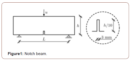
As aforementioned for considering the size effect, authors decide to choose specimens which only difference between those is the size. So for this reason three simply supported notched beams with free ends (assuming constant values of tensile strength ft) were selected. These beams were performed with three different beam sizes of a similar geometry h*Lt: 8*32 cm2 (called small size beam), 16*64 cm2 (called medium size beam), 32*128 cm2 (called large size beam) (h – beam height, Lt – total beam length), in Fig. 1. The span length L was equal to 3h for all beams. The size of the beams was similar as in the corresponding experiments carried out by Le Bellego et al [10] (Figure 1).
Finite Element Model
Finite element analysis (FEA) was performed to develop reliable models based on experimental results which can simulate the behavior of three-point bending notch beam. Three FE models of three-point bending notch beam with different size were developed using ABAQUS/CAE. All specification such as boundary condition, loading, material and mesh are same in the simulation and just the size of the beam is different. Initially calibration parameters for small size beam has done. For this purpose, an objective function has defined. The value of this objective function was performed as square of difference value between loads from experiment and numerical modeling in the same deflection for small size beam. Then the calibrated parameters was used for all beams with difference size in the definition of CDP. In the simulation for beam part the linear tetrahedral element (C3D4) was used. The mesh size of element in the middle of the beam 5 mm and in the rest of the beam 10 mm was chosen which has best result in the simulation compare to the experiment. The analysis was performed in step-1 (static-general) a step after initial step. The loading was achieved by defining a reference point at top of beam and assigning a prescribed displacement to the reference point.
Calibration of Input Parameters
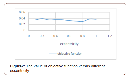
As discussed before for the calibration the small size beam with dimension h*Lt: 8*32 cm2 was created in ABAQUS/CAE. The aim of the procedure was to definition an objective function and minimize the objective function for each parameter by assuming constant value for other parameters. So, the effect of each parameter can be checked in the result of finite element analysis (FEA). Value of objective function versus different eccentricity with ψ=20 and viscosity parameter=0.0009 was performed in figure 2 (as shown in the fig. 2) changing in the eccentricity has low effect on the value of objective function and the value of objective function when the ϵ=0.8 is minimum (Figure 2).
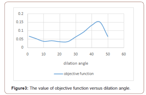
Other parameter that need to calibration is dilation angle so for this mention all other parameters assumed constant. Value of objective function versus different dilation angle with ϵ=0.5 and viscosity parameter=0.0009 was performed in fig.3.as shown in the fig. 3 the value of dilation angle, ψ=25, can minimizing the objective function (Figure 3).
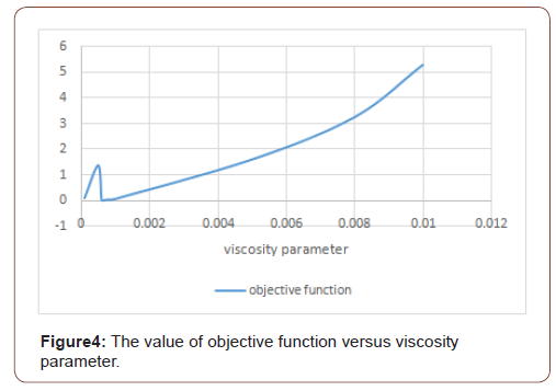
The last parameter has been checked for the calibration is viscosity parameter and observed that changing in the value of vis-cosity parameter has more effect on the value of objective function rather than to other parameters. Value of objective function versus different viscosity parameter with ψ=20 and ϵ=0.5 was performed in fig. 4as shown in the fig. 4 the value of objective function when the viscosity parameter=0.0006 is minimum (Figure 4).
Finally, three parameters dilation angle (ψ), eccentricity (ϵ) and viscosity parameter have been calibrated by using small size beam. Summery result for selected parameters which minimize the objective function were performed in (Table 1).
Table:Selected parameters for minimize objective function.

Results and discussions
Small size beam
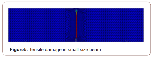
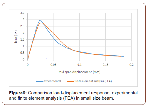
After calibration three parameters dilation angle (ψ), eccentricity (ϵ) and viscosity parameter, it is necessary to use these calibrated parameters in the definition of concrete damage plasticity for concrete in the finite element simulation. Initially in the modeling of small size beam this calibrated parameter have used. The contour of tensile damage in the result of finite element analysis (FEA) was performed in the fig. 5 as shown in the fig. 5 the critical path for tensile damage is located in the middle of the beam and element in this path has fully damaged. The load-displacement curve from experimental and finite element analysis (FEA) for small size beam was performed in fig. 6. As shown in the fig. 6 the result of numerical simulation and experiment has good matching. Plus, the peak of the curve in finite element analysis result located in place very close to the peak of the curve in experiment (Figure 5, 6).
Medium size beam
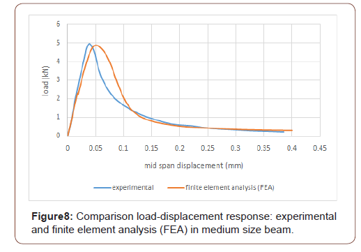
Medium size beam with dimension h*Lt: 16*64 cm2 was created in ABAQUS/CAE. In the finite element simulation, all specification such as boundary condition, loading, material, mesh type and mesh size are same with small size beam. Actually the purpose of using same material in the finite element simulation is in definition concrete damage plasticity using same compressive and tensile behavior for concrete and in the plasticity section use the calibrated parameter for dilation angle (ψ), eccentricity (ϵ) and viscosity parameter and use default value for and Kc. The only difference between medium size and small size beam is the size. The contour of tensile damage in the result of finite element analysis (FEA) was performed in the fig. 7 as shown in the fig. 7 the critical path for tensile damage is located in the middle of the beam and element in this path has fully damaged like small size beam. The load-displacement curve from experimental and finite element analysis (FEA) for medium size beam was performed in fig. 8. As shown in the fig. 8 the result of numerical simulation an experiment has good matching, in addition, the load capacity of the beam from numerical is very close to the load capacity of the beam from experiment (Figure 7, 8).
Large size beam
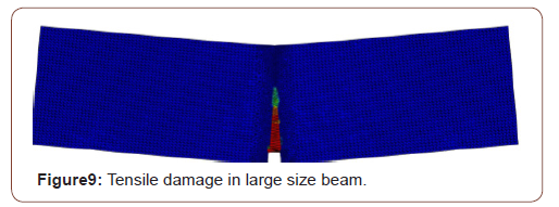
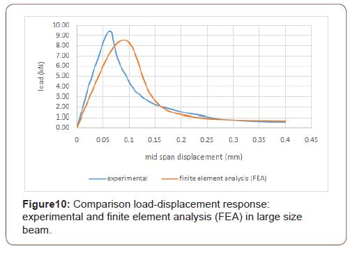
The last beam that created in ABAQUS/CAE for checking the size effect on the concrete damage plasticity in this paper is large size beam with dimension h*Lt: 32*128 cm2. As aforementioned like medium size beam, In the finite element simulation of large size beam all specification such as boundary condition, loading, material, mesh type and mesh size are same with small size beam. Actually in definition concrete damage plasticity using same compressive and tensile behavior for concrete and in the plasticity section the calibrated parameter for dilation angle (ψ), eccentricity (ϵ) and viscosity parameter and default value for and Kc have used. The only difference between large size beam and small size beam is the size. The contour of tensile damage in the result of finite element analysis (FEA) was illustrated in the fig. 9.as shown in the fig. 9 the critical path for tensile damage is located in the middle of the beam and element in this path has fully damaged like two other beams. The load-displacement curve from experimental and finite element analysis (FEA) for large size beam was performed in fig. 10. As shown in the fig.10 the result of numerical simulation and experiment has good matching. furthermore, the load capacity of the beam from numerical is very close to the load capacity of the beam from experiment (Figure 9, 10).

Conclusion
One of the important and necessary characteristics for each material model is its independency on the size of the problem that is used for modeling. Regarding this issue, in this paper, an attempt was performed to investigate the order of dependency of the concrete damaged plasticity model (CDP) of the ABAQUS software to the size of the structure. Three different concrete beams subjected to three-point-bending test were simulated by the ABAQUS software and CDP model was used to model the behavior of concrete material. A unique set of input parameters of CDP model used for all the above-mentioned beams. The obtained load-displacement curves revealed that with the same set of input parameters, the CDP model can predict well the behavior of the beams with three different sizes. This result demonstrates that the CDP model is an independent model to the size of the structure and can be used for modeling all concrete structures with arbitrary geometrical dimensions.
To read more about this article...Open access Journal of Civil & Structural Engineering
Please follow the URL to access more information about this article
To know more about our Journals...Iris Publishers


No comments:
Post a Comment