Authored by Buse Şeyda Hocaoğlu*
Abstract
With the development of the world and human beings’ rush to get somewhere, the need for tunneling has increased. Solutions have been made with the methods of end-to-end elements searched for a more straightforward resolution and visual thinking of tunnel projects that are complex and difficult to foresee. Thanks to these methods, geotechnical problems have been more easily detecting, and solutions have been producing in a short time. Several finite element methods have been developed in line with technology development and research. In this study, Plaxis, Flac, ABAQUS, Diana, Midas GTS NX programs, which are some of these programs, were briefly introduced, and tunnel projects solved with the mentioned programs were given
Keywords:Finite element method; Tunnel project; Plaxis 2D/3D; Flac 2D/3D; Geotechnical
Introduction
The finite element method is a numerical method that thoroughly solves mixed engineering problems. It was first developed and used in 1956 for stress analysis of aircraft bodies. It has been understood that it can also solve engineering and applied sciences problems in the following years. Over the years, the finite element method and solution techniques have developed rapidly and have become one of the best methods used to solve many problems today. The method is so popular for many engineering areas because a generic computer program can only solve any problem by changing the input data. By separating it into finite elements suitable for the structure of a problem, it implements a solution method in the form of a low energy level of internal and external forces on the obtained elements and then combining these elements. As a result, the system’s features, border conditions, sudden or continuous changes of external loads can be easily examined. It is also possible to reduce the element sizes in the constant system’s desired parts for the detailed examination of a region [1,2]. It can list the advantages of finite element methods: geometry allows complex problems to be solved, easily applicable in systems with different and complex material properties, easy to include border conditions in the fundamental equations of the system, and the use of the same model to solve many problems [2]. The disadvantages of the finite element method can be listed; found that the accuracy of the result obtained depends on the accuracy of the data, that the separation of regions requires experience to get an acceptable correct result, and that the accuracy of the result obtained is observed, and that the physical problem must be investigated well [2]. The finite element method has been used for 30 years in many engineering areas and was introduced in geotechnical engineering in 1996. The most important reason for this is that geotechnical engineering has complex issues and takes time to solve them. When used correctly, this method can provide accurate results for practical geotechnical engineering problems. A good analysis allows the engineer to understand the problem better [3]. The Finite element method can be applied to any linear-elastic medium. However, it requires many limitations for the implementation of the method in geotechnical engineering problems. In the method, material behavior is formulated by associating with changes between shape changes and total stress. In contrast, in geotechnical problems, the total tensor is decompressed into cavity water pressures and effective stresses, and material behavior is often expressed in terms of effective stresses. Most of the Geotechnical problems are interacting with the structure and the ground. Therefore, in analyzing these types of problems, it is necessary to use an intermediate surface between the structure and the soil. As a result, it is required to make changes to correctly apply the finite component method in geotechnical engineering [2]. To get a realistic result in analyzing finite elements for geotechnical engineering problems, the procedures are carried out step by step (phased loading, phased excavation). There are two benefits to ensuring that analysis can be performed in stages. First, the geometry changes at each step if the analyzes add or remove the padding. The change in geometry can be modeled by adding or removing elements from the network of end elements. Secondly, in the analysis, the ground properties change at each loading stage due to the change of stresses in the soil mass [2]. As a result of the study of finite elements in geotechnical engineering problems, parameters such as stresses, cavity water pressures, lateral and vertical movements, and groundwater flow are determined [1]. Today, programs used in finite element methods are used in many areas, such as ground mechanics, fluid mechanics, aircraft engineering, nuclear engineering, rock mechanics, etc. It can be studied by selecting the program that will give the most realistic results for problems. Examples of these programs include Plaxis 2D/3D, FLAC 2D/3D, ABAQUS, Diana, Midas GTS.
Methods
Plaxis 2D/3D
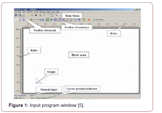
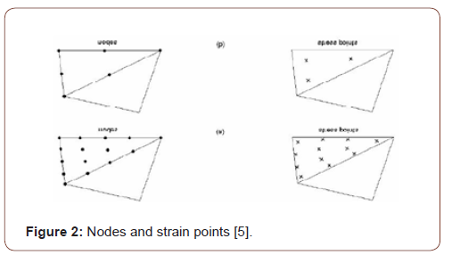
Plaxis 2D/3D, one of the finite element’s programs, is a program developed to analyze geotechnical engineering problems. The program consists of an input program, calculation program where analysis is performed, output program that graphically presents the study results, and curve program that enables the creation of the desired chart with the results obtained (Figure 1). This program is used to design projects where deformation and stabilization analyzes are needed, strain-shifting, ground structure interaction, loading conditions, carrying power, consolidation, current network, ground dynamics, and material are varied and bring real-life results [4]. According to the method of finite, a continuous environment is divided into many elements. The node points on each element have a degree of freedom. During the creation of a network of finite elements in the Plaxis program, the cells are divided into triangular elements with 6 or 15 nodes (Figure 2). Even if it takes a little more time to calculate the stresses and migration surfaces more realistically, it is better to select the 15-node element. The displacement is calculated at node points during the finite element calculation [4] (Figures 1,2).
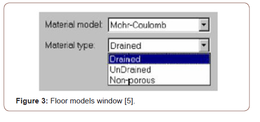
Under the main heading Plaxisde Material Sets, the floor and structural members (Soil & Interface, anchor, Beam, and Geotextile) can be defined. The Plaxis program has several floor models, such as Mohr-Coulomb (MC), Hardening Soil (Model-HS), soft Soil Creep (Model-SSC), which are widely used for analyzing floor mechanics problems (Figure 3) [4].
Flac
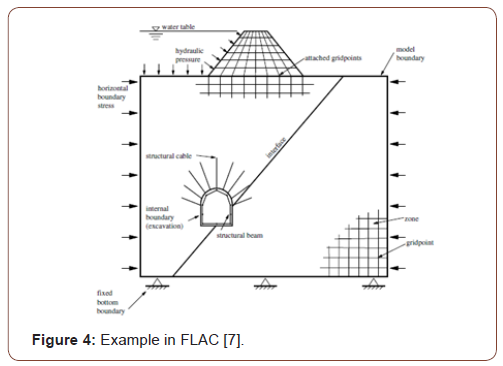
FLAC is a program that uses the use of a finite element type to numerically or numerically examine the mechanical behavior of continuous media in equilibrium or progressive plastic yield. In the program, creating a network of finite differences defined by the user via elements can detect the behavior of materials such as ground and rock at the level of plastic flux. Every element behaves by the previously specified linear or non-linear stress-shape defining feature against forces applied under boundary conditions [6]. Thanks to the intermediate surface formulation in the software, the interaction between two sonly differences networks that are interconnected but are likely to divest or slide along a surface, such as a fault structure, can also be modeled. Hydrostatic pressure used in liquefies research or design of dams is carried out by applying fluid mechanics formulation. Structural elements are used to model entities such as anchors and flooring nails. In addition to all these, it is possible to perform realistic modeling with this software by applying static and dynamic boundary conditions. Although FLAC has been developed for Geotechnical engineering applications, it is also widely used in many research areas such as mining engineering, underground structures, and rock mechanics (Figure 4) [6].
The use of the FLAC finite element program in some engineering applications is as follows:
1. Calculation of transport capacities and deformations according to ground and loading conditions in the design of slope and foundations.
2. In the ground structures, calculate the safety coefficient in the stability analysis of fillers and slope.
3. Assessing the fault structure and impact of the interest structure in mining research projects.
4. Design of floor anchorages, rock bullion, ground nail, and support systems in geotechnical problems.
5. Examination of the dynamic effects that will occur resulting from vibration and explosion in tunnel and mine excavations.
6. performing seismic analysis of structures in the design of earth filling dams.
The solution of the Flac finite elements method consists of the three-step approach given below. The solution method for FLAC finite components consists of the following three-stage process. First, the finite differences phase, a limited time, and the change over field linear default variables are estimated by the time and finite differences of the first degree. Second, the model’s deposition phase: An equivalent environment replaces the continuous environment by a deposition. In the new environment, all forces are assumed to be gathered at the nodes of a three-dimensional network. Third, the dynamic solution phase is used to access the system’s balanced state, whose inertia terms in motion equations are analyzed as numeric agents [6].
Abaqus
Abaqus is a finite element method that works through a detailed analysis of engineering problems by creating realistic computeraided models (Figure 5).
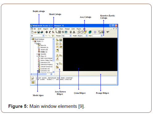
It offers the ability to analyze linear and nonlinear projects that are difficult to solve due to the different material models and finite element types involved [8]. The program consists of five essential software: Standard, Explicit, CFD, Electromagnetic, and CAE. ABAQUS/Standard uses solution technology, ideal for static and low-speed dynamic events where highly sensitive stress solutions are critical. Within a single simulation, it is possible to analyze a model in both the frequency and time zone. Standard is closed finite elements software that can perform static and dynamic analyzes. Their solution uses advanced material and element features. It can also perform acoustic and associated doubleacting analyzes, and the plastic injection can be used in conjunction with various programs for mold analysis results [8]. Abaqus/Explicit, a particular purpose finite element analyzer that uses an open integration scheme to solve many complex contacts, nonlinear systems under transient loads. At the same time, automotive is particularly suitable for simulating short transient dynamic events such as collision capability and ballistic impact. It is a handy software for simulating semi-static events, such as handling nonlinear behavior and the rounding of hot metal effectively.
Collision tests can be used for dropping tests and resolution of strain problems [8]. Abaqus/CFD, it is the software that Abaqus offers to solve computational fluid dynamics problems. It can solve nonlinear fluid-structural and fluid-thermal problems. Real results are achieved when used in nonlinear structural-flow and heat- flow applications [8]. Abaqus/Electromagnetic offers an advanced computational solution of electromagnetic problems [8]. Abaqus/ CAE is a software used for both the modeling of mechanical components and its analysis and visualizes the analysis results. Thanks to its intuitive interface, it is user-friendly in modeling, research, and result visualization [8].
Diana
Chan in 1988, designed for dynamic, static, and consolidation analysis of geomechanical problems. It is a 2-dimensional element program that contains plane deformation and asymmetric analysis. The program has five ground models. It can be rank these models as a linear elastic model, Coulomb changing with average effective environmental pressure, a general elastic model with friction envelope, elastic-full plastic Mohr-Coulomb, original glass clay Pastor-Zienkiewicz Mark-III models. The DIANA program requires four input files for each finite element analysis to be performed. These input files consist of mesh, data, introduction, and earthquake files. Running an analysis requires these input files to be created in a specific order [10]. The network file defines the geometry of the finite element network to be used in the analysis. The geometry of the defined floor model is divided into smaller regions, creating a finite element net. The input file ‘DYNMGEN’ is used to prepare the network file [10]. The data file contains control data to be used to perform finite element analysis. All technical information about finite element analysis is stored in this file [10]. The Initial file creates the initial conditions for finite element analysis. This file’s data contains the initial speed, start time, start displacement, maximum displacement norm, earthquake status, initial acceleration, and internal parameters of the ground model. The ‘DYNINT’ input file is used to prepare the initial data file [10]. The earthquake file is the last input file required for finite element analysis. The important aspect to be considered in preparing this input file required for dynamic analysis is the type of earthquake and the scale factor. For dynamic analysis, the desired load transaction type and transaction scale must be created in the ‘DYNEQK’ input file and encoded in the scale factor data file [10].
Midas GTS NX
MIDAS GTS NX is an important method of finite elements for geotechnical and tunnel analysis systems. It can model geological problems that are difficult to model with advanced technology [11]. In Midas GTS NX, geometry is modeled in 2 shapes. The first is that geometry is drawn in 2D or transferred from drawing programs. A network of 2D finite elements is then created and offset to the 3rd dimension, resulting in a model of 3D finite elements. This method may not be available for complex geometries. The other method is to create 3D geometric objects by giving dimensions 3rd dimension in 2 sizes or transferred using the command “extrude” [12].
Examples Using the Finite Element Method
Tunnel example with Plaxis Program
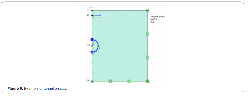
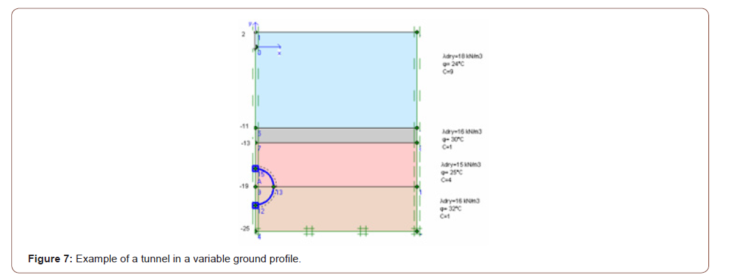
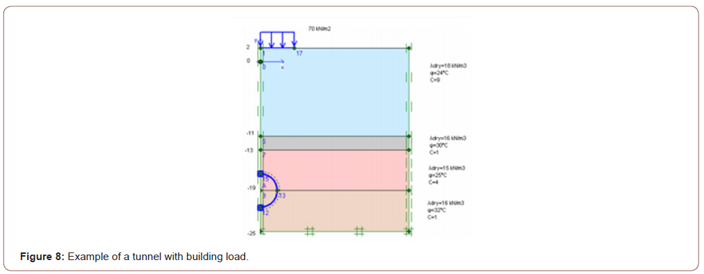
In this tunnel project application, the Plaxis 2D program, one of the finite programs, has calculated deformations that can be caused by the passage of tunnels. In line with these deformations, ground improvement methods have been implemented. The Plaxis program is selected for this application because complex boundary conditions and nonlinear material behavior allow systematic programming in solving challenging and complex problems such as non-homogeneous materials. 6 different cases have been explored in this application. In the first application, the whole floor is assumed to be clay, and the tunnel is added. (Figure 6). In the second application, tunneling is performed in the clay and sandy variable ground profile with different ground parameters (Figure 7). The deformation of the floor surface and the deformation of the tunnel covering have the same value and have increased by 50,92 mm. In the third application, he implemented a building load without improving the previous project (Figure 8). The deformation of the floor surface has increased to 87,41 mm. Due to the tunnel covering’s building load; the deformation value has risen to 52, 57 mm. Improved soil with geotextiles and sealants before applying building load in the fourth application (Figures 6-9).
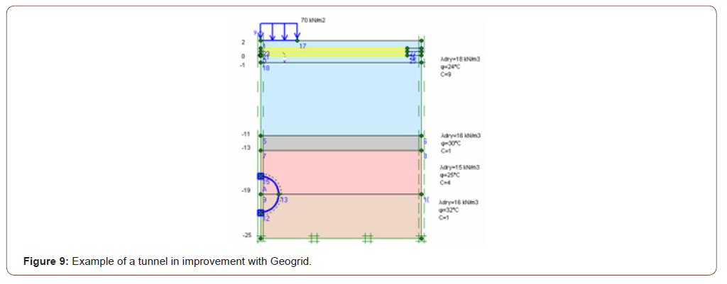
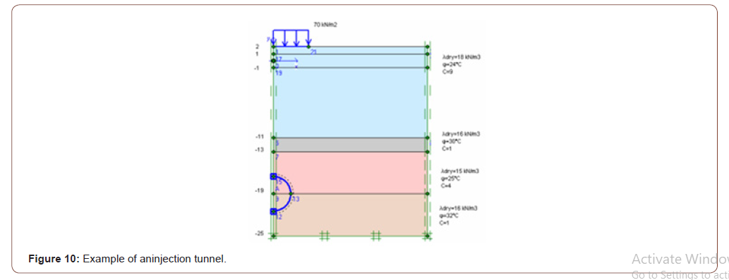
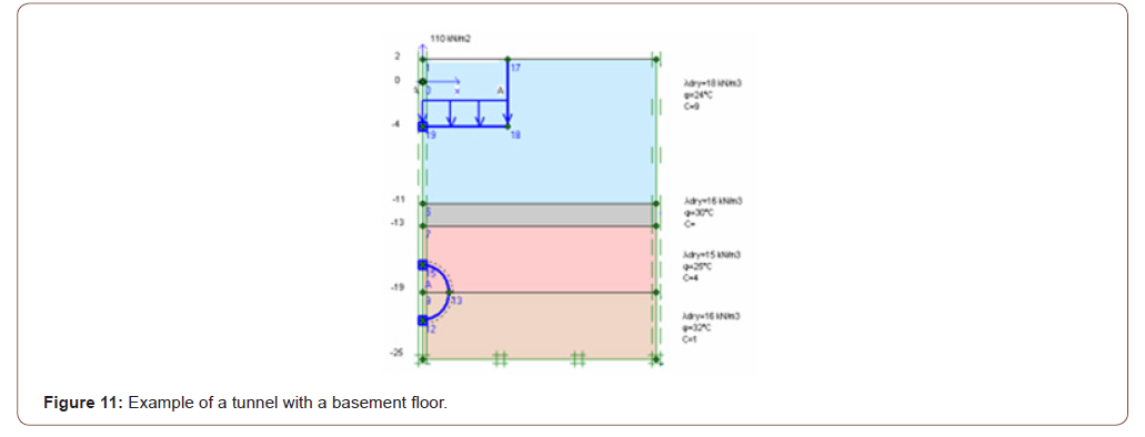
Due to the optimization, the deformation of the floor surface has been retightened to 67,49 mm. The deformation value in the tunnel covering is close to the previous example and has dropped to 51,71 mm. A 2 m thick floor injection method is implemented as an enhancement (Figure 10). As a result of this optimization, the soil surface’s deformation has been retightened from 67,49 mm to 58,62 mm. The deformation value in the tunnel lining is 52.54 mm. The sixth application assumes that a 5-story building with two basements is built on the ground, and the deformation value in the tunnel coating is 50.51 mm (Figures 10,11).
As a result of these examples, finite element programs must be analyzed to ensure that new structures built after tunnel construction are constructed without damaging the tunnel and existing structures. A non-damaged construction must be carried out by determining suitable solutions to the problems that will arise. Before applying a building load, improvements can be made to the characteristics of the floor, thus setting the seating values on the floor surface to lower values. It is important to maintain the ground during tunnel construction and select two to maintain the tunnel’s stability. The groundwater check must be carried out from the start of the project. The tunnel is to be built must be checked that it will not damage structures around it [13].
Tunnel example with FLAC 3D Program
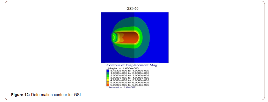
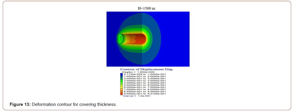
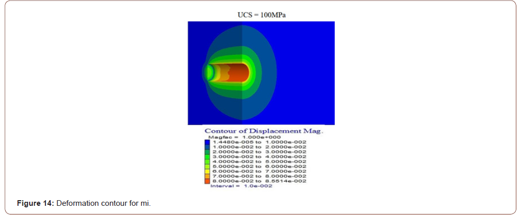
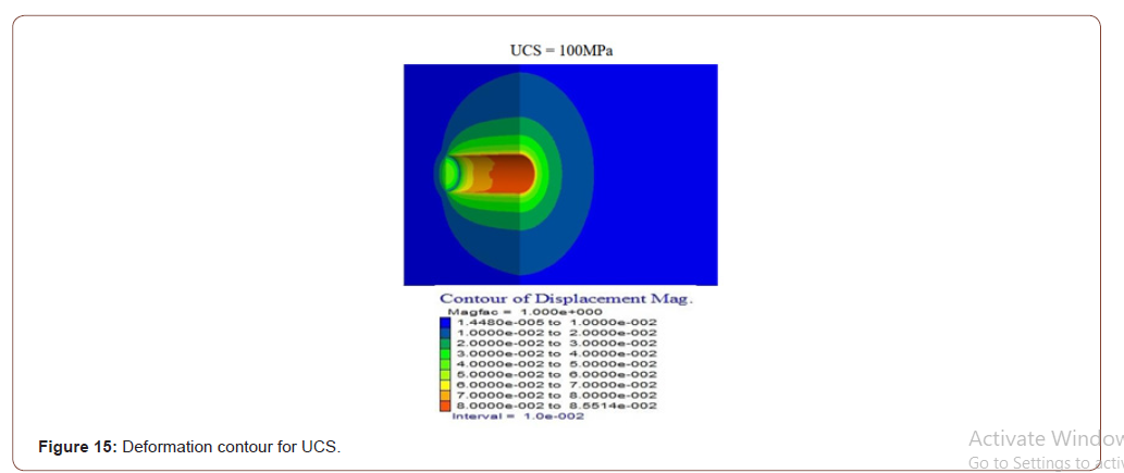
Pressed floors can cause many problems, such as the collapse of supports due to heavy load, groundwater, excessive closure of pile profiles, or destruction of tunnel support. Therefore, before tunneling on such floors, the type and severity of the jamming that may occur should be investigated in advance. A specific formula produced by Hoek-Brown is used to predict the possibility of jamming and to analyze the jam. Flac 3D, Finite elements program, was used to determine the Hoek-Brown criteria parameters to be taken into account in the analysis of trapped floors in this application. For these studies, four Hoek-Brown input parameters are considered and modeled mainly: Rock mass parameters GSI (geological strength index), UCS (single-axis press strength), MI (Hoek material constant), and H (covering thickness). Code (FISH code) has been written by the Hoek-Brown criteria, as Flac3D is based on Mohr-Coulomb criteria. Numerical modeling results using GSI, H, UCS, and mi variables according to Hoek and Brown defeat criteria are presented separately as deformation contours and plastic zone contours. Deformation contours have been found to have a significant reduction in deformation contours around the tunnel as the GSI value increases from three-dimensional numeric models with different GSI values (Figure 12). In line with the results obtained by giving different tunnel cover thickness values, it was determined that the deformations around the tunnel increased rapidly as H increased (Figure 13). As a result of the deformation contours for the different mİ values from the three-dimensional numeric models, the mİ value has increased. In contrast, the deformation values have been found to have very little reduction than the other parameters (Figure 14). Thus, it is understood that the effect of mİ value on the potential for compression is not an important parameter. A significant reduction in deformation around the tunnel has been identified as the UCS value increases about deformation contours from three-dimensional numerical models using different single axis thrust strength values (Figures 12-15).
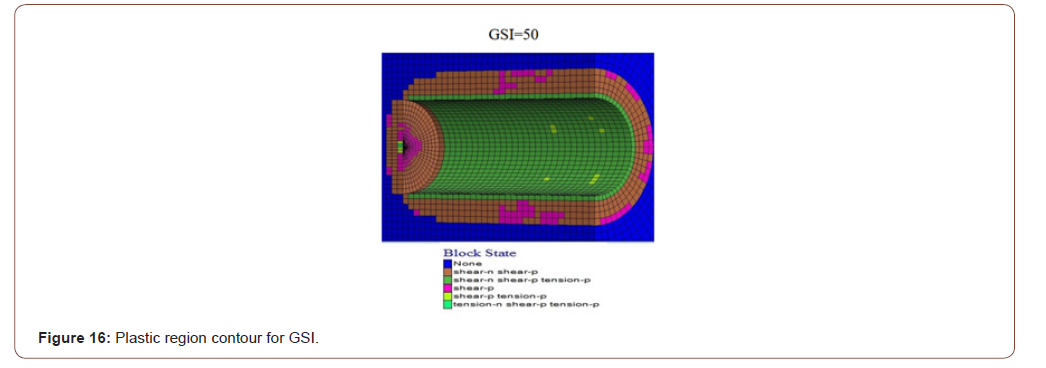
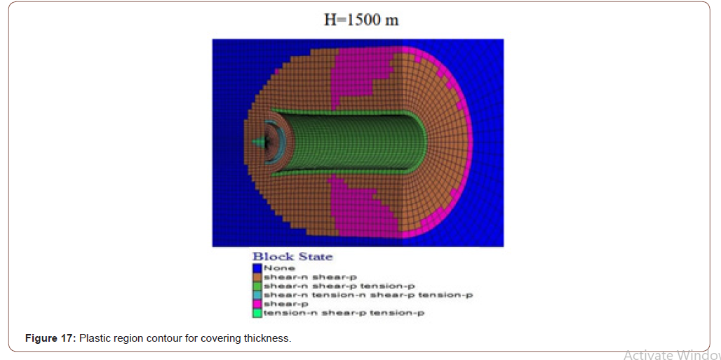
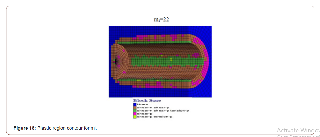

As a result of different GSI values, plastic zone contours decreased significantly in the thickness of the plastic area around the tunnel as the values increased (Figure 16). Using different cover thicknesses, it was determined that the value of plastic zone thickness increased as it increased (Figure 17). Using another mi value, it was determined that the plastic zone thickness values decreased due to the increase (Figure 18). While a change in the plastic zone size was observed with the increase in MI value, it was determined that this determined change MI parameter was not a useful parameter on the plastic zone. Using different single axis thrust strength values has determined that the plastic zone thickness around the tunnel decreases as the UCS value increases (Figures 16-19).
In parallel with the result of the plastic region radius, analyzes, and deformation analysis, the study’s parameters revealed that GSI, UCS, and H were the most influential parameters. It should be considered that the effect of the MI parameter will also change when the fixed parameters are changed, even though the impact of the MI parameter is low [14].
Result
As a result of developing technologies and research, existing programs have been designed and provided ease of solution to many engineering problems. The programs in which the method of finite elements was applied increased over time. In this way, almost every engineering branch has used appropriate programs for its problems. Many complex and time-long issues have been solved in fewer time thanks to these programs. Questions are broken down into pieces and solved in more detail, resulting in more realistic results. The development of programs and the introduction of 3D solutions have made it easier to understand problems and solutions. This makes tunnel projects easier to solve, and errors can be detected. Problems encountered during the opening phase of tunnels have been quickly resolved, and necessary improvements have been made. As technology evolves and people seek more realistic results, the finite element methods will continue to grow and develop.
To read more about this article...Open access Journal of Civil & Structural Engineering
Please follow the URL to access more information about this article
To know more about our Journals...Iris Publishers


No comments:
Post a Comment