Authored by Osama Mohammed Elmardi Suleiman Khayal*,
Abstract
The sand mold tooling development comprises; determining the parting line, designing and making the patterns, cores, and cores prints, gating system, feeding system, and the flask.
This paper is pertinent to the creation of a program called Sand Casting Mold Design (SCMD) which represents part of an expert system used for sand casting mold tooling development.
Keywords: Sand Casting Mold Design (SCMD); Parting line; Pattern; Core; Core print; Gating system; Feeding system; Flask
Introduction
In sand casting mold design, the tooling development is a critical activity linking product design and manufacturing. Tooling development can be further classified as design of main cavity (or the pattern for producing the cavity), other cavities and accessories. The main cavity, produced by bringing together two or more segments of molds, involves selection of the best orientation of part in the mold and determining the parting line. Internal cavities in the part, such as holes and undercuts are produced by cores. This requires identification of cored features, and design of cores (i.e. including their supports, called prints). Proper allowances have to be incorporated in the mold cavity and cores considering part shrinkage, draft or taper to facilitate removal of the pattern from sand, subsequent machining, and fillet radius. Other cavities include gating channels (sprue, slag trap and runner) to lead molten metal into the mold and feeders or risers (number, location, shape, and dimensions) to compensate for volumetric shrinkage. The last step in tooling development is determining the dimensions of the flask which represents the frame that holds the two parts of the mold (i.e. the cope and the drag) [1-5].
The Sand-Casting Mold Design (Scmd) Program
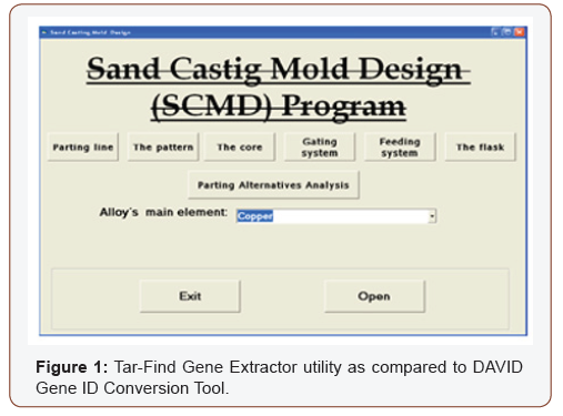
One part of expert system for sand casting mold tooling development is the Sand-Casting Mold Design (SCMD) which is an attendant program leading the user step by step through the design stage, and it is created using Visual Basic 6.0 program language. Besides the main screen (Figure 1) the SCMD program contains seven subprograms named [6-9].
• Parting line.
• The pattern.
• The core.
• Parting alternatives analysis.
• Gating system.
• Feeding system.
• The flask.
The Scmd Main Screen
When the user starts the SCMD program the main screen form called Sand Casting Mold Design appears. At the bottom of it there is a frame contain Exit button which closes the program after warning massage and Open button which opens the Parting line subprogram and leads the user step by step through the design stage. The user also can access every subprogram by clicking the button of its name in the middle of the main screen. Table 1 shows the abbreviations of the main screen flow chart.
Table 1: Abbreviations of the main screen flow chart.

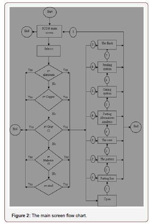
Any button in the main screen cannot respond and give a warning massage till the user select the Alloy’s main element from the Dropdown List at the middle of screen. The flow chart of the SCMD program logic is given in Figure 2.
The Scmd User Interface
Every subprogram of the SCMD program consists of number of windows (Visual Basic forms) and these windows interact with the user through common features as shown in Figure 3.
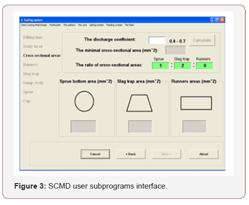
At the top of the window there is title bar which gives the name of the subprogram and under it there is a menu bar which consists of seven drop down list menus named with subprograms names.
The steps of the subprogram are found at the left side of the window and all of it are dim except the current one.
At the bottom of the window there is four command buttons. The left one is the Cancel button which closes the program after warning message. The Back and the Next buttons allow navigation through the steps of the program. The rights one is the About button which opens help file which contains information about the current step of the subprogram. In some windows (i.e. like Feeder dimensions window) there is red button when it is clicked it opens a file that contains information about specific scope.
The middle of the window represents the operation area which contains all input and output and tools like Text Boxes, Command Buttons, Option Buttons, Labels, List Boxes, Check Boxes, Combo Boxes, and interpreted Pictures. The Text Boxes (i.e. the main input and output tools) have three types:
• White color Text Box for input data;
• Gray color Text Box for output data that can’t be changed;
• Green color Text Box for output data that can be changed.
The Parting Line Subprogram
The Parting line subprogram has the four following (windows) steps:
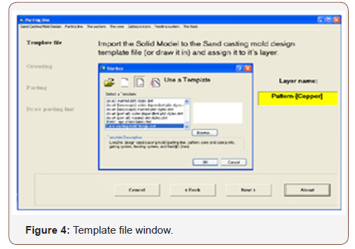
1. Template file (Figure 4): leads the user to import the Solid Model to the Sand-casting mold design template file (or draws it in) and assigns it to its layer.
2. Orienting: Advice the user to orient the solid model and define the parting line using the Orientation tool on the Parting line toolbar.
3. Parting: Advice the user to have parting alternatives in which the solid model is divided into numbers of parts using the Parting tool on the Parting line toolbar.
4. Draw parting line: Advice the user to draw the parting line on the contour of the parting surfaces using the Circle, Polyline, line, or Arc tools on the Parting line or the Core toolbars as aid tools and assigns it to Line [Parting line] layer.
The Pattern Subprogram
The pattern subprogram has five steps (windows) which are:
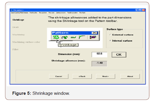
1. Shrinkage (Figure 5): Gives the user recommended shrinkage allowances after determining the dimensions and surface type.
2. Draft: Gives the user recommended draft angle after determining the pattern material, surface height, and surface type.
3. Machining: Gives the user recommended machining allowances after determining the surface type.
4. Machining surface color: Advices the user to add color to the surfaces of pattern to be machined using Machining surface color tool on the Pattern toolbar.
5. Fillet: Gives the user recommended fillet radius after determining the wall thickens.
The Core Subprogram
The core subprogram has four steps (windows) which are:
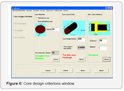
1. Core design criteria (Figure 6): Leads the user to design the cored holes and undercuts by checking three design criteria (Core diameter, Core aspect ratio, and Inter-cores distance).
2. Core extrusion: Advices the user to produce the core by first draws polyline or circle (using Core shape layer) in the section area circumference of the cavity and then uses Extrude core tool to convert them to solid.
3. Core prints: Gives the user the core print layer name and recommended length after determining the core type and if the hole machined or unmachined.
4. Core analysis: Leads the user to analyze the force on the core and core prints by checking two design rules after determining geometrical and material data.
The Parting Alternatives Analysis Subprogram
The Parting Alternatives Analysis subprogram has two steps which are:
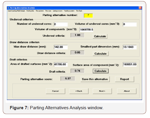
1. Parting Alternatives Analysis (Figure 7): Leads the user to make the right decision about the most suitable parting line (that optimizes number of undercut cores, draws distance, and drafts design criteria) when multiple parting alternatives are available.
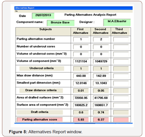
2. Alternatives Report (Figure 8): Leads the user to abstract and print the parting alternatives analysis result.
The Gating System Subprogram
The Gating system subprogram has eight steps which are stated as follows:
1. Filling time (Figure 9): Leads the user to calculate the time of mold filling after determining the wall thickness (predominant) of the casting, the mass of the casting, and the coefficient A whose values is depending on component alloy.
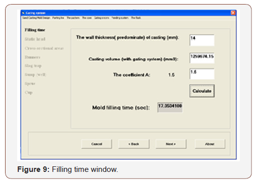
2. Static head: Leads the user to calculate the static head after determining some dimensions. The static head step has two windows which open depending on alloy main element.
3. Cross-sectional areas: Lead the user to calculate the crosssectional areas of sprue bottom, slag trap, and runners after determining some values.
4. Runners: Give the user the layer name, and recommended dimensions for the runner.
5. Slag trap: Gives the user the layer name, and recommended dimensions for the slag trap.
6. Sump (well): Gives the user the layer name, and recommended dimensions for the sump.
7. Sprue: Gives the user the layer name, and recommended dimensions for the sprue.
8. Cup: Gives the user the layer name, and recommended dimensions for the cup. The Cup step has two windows which open depending on alloy main element.
The Feeding System Subprogram
The Feeding system subprogram has three steps which are given as follows:
1. Feeder dimensions (Figure 10): Gives the user the layer name, and recommended dimensions for the feeder after making some selections and determining some values.
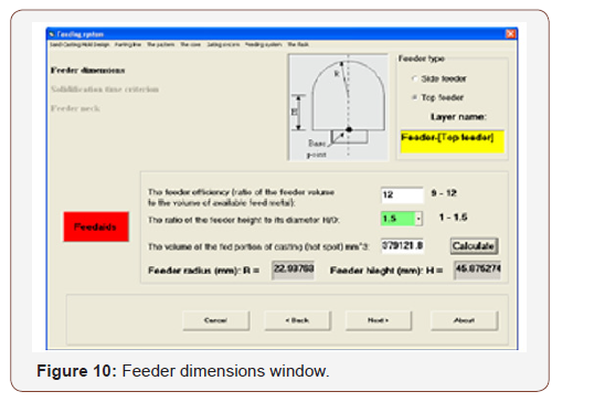
2. Solidification time criterion: Enables the user to check the solidification time criterion. The solidification time criterion step has two windows which open depending on alloy main element.
3. Feeder neck: Gives the user the layer name, and recommended dimensions for the feeder neck and enables him to check the feed Path criterion. The Feeder neck step has four windows which open depending on the feeder type (side or top) and the alloy main element.
The Flask Subprogram
The Flask subprogram has one step which is:
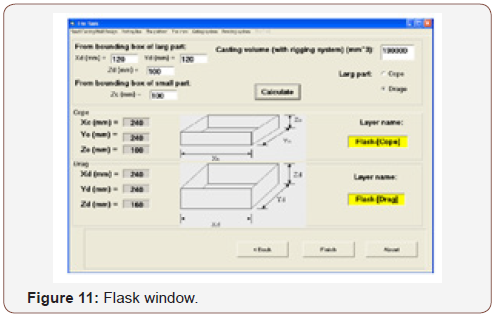
Flask (Figure 11): Gives the user the layer names, and recommended dimensions for the cope and drag of the flask which conforms with the weight and dimensions of the casting.
Conclusion
Beside AutoCAD template file and customization menus and toolbars the Sand-Casting Mold Design (SCMD) program constitutes an expert system for sand casting mold tooling development. This expert system was tested by designing known casting components in Sudan Railways Foundry, and the roles of Sand-Casting Mold Design (SCMD) program are to:
• lead the user step by step through the design stage.
• provide the user with information for every design stage.
• hold the database of sand casting and casted metals and give it to the user directly or after performing mathematical processing.
• receive data from the user and processing it.
• perform the design calculation and give the result to the user with ability to modify this result.
• perform the analysis calculation and give the decision to the user.
• give the user the possibility of printing the final reports and drawing of some mold parts with its dimensions to be ready for manufacturing.
To read more about this article...Open access Journal of of Engineering Sciences
Please follow the URL to access more information about this article
https://irispublishers.com/gjes/fulltext/sand-casting-mold-design-scmd-program.ID.000566.php
To read more about this article...Open access Journal of of Engineering Sciences
Please follow the URL to access more information about this article
https://irispublishers.com/gjes/fulltext/sand-casting-mold-design-scmd-program.ID.000566.php


No comments:
Post a Comment