Authored by Osama Mohammed Elmardi Suleiman*,
Abstract
New numerical results are generated for in – plane compressive biaxial buckling which serve to quantify the effects of lamination scheme on buckling loading. The results indicate that the symmetric laminate is stiffer than the anti – symmetric one. This phenomenon is caused by coupling between bending and stretching which lowers the buckling loads of symmetric laminate.
Keywords: Lamination scheme; Biaxial buckling; Classical laminated plate theory; Finite element; Fortran program; Composite laminated decks plates
Introduction
The motivation that led to the carrying out of the present study has come from many years of studying classical laminated plate theory (CLPT) and its analysis by the finite element (FE) method, and also from the fact that there does not exist a publication that contains a detailed coverage of classical laminated plate theory and finite element method in one volume. The present study is an attempt to fulfill the need for a complete treatment of classical laminated theory of plates and its solution by a numerical solution.
The material presented is intended to serve as a basis for a critical study of the fundamentals of elasticity and several branches of solid mechanics including advanced mechanics of materials, theories of plates, composite materials and numerical methods.
The problem of critical buckling loads of laminated composite plates is analyzed and solved using the energy method which is formulated by a finite element model. In that model, four nodded rectangular elements of a plate is considered. Each element has three degrees of freedom at each node. The degrees of freedom are the lateral displacement w, and the rotations ϕ and ψ about the y and x axes respectively.
The effects of lamination scheme on the non – dimensional critical buckling loads of laminated composite plates are investigated.
The material chosen has the following properties:
E1 / E2 = 5,10, 20, 25, 40;G12 = G13 = G23 = 0.5E2 ;v12 = 0.25 .
Several numerical methods could be used in this study, but the main ones are finite difference method (FDM), dynamic relaxation coupled with finite difference method (DR) as is shown in references [1-8], and finite element method (FEM).
In the present work, a numerical method known as finite element method (FEM) is used. It is a numerical procedure for obtaining solutions to many of the problems encountered in engineering analysis. It has two primary subdivisions. The first utilizes discrete elements to obtain the joint displacements and member forces of a structural framework. The second uses the continuum elements to obtain approximate solutions to heat transfer, fluid mechanics, and solid mechanics problem. The formulation using the discrete element is referred to as matrix analysis of structures and yields results identical with the classical analysis of structural frameworks. The second approach is the true finite element method. It yields approximate values of the desired parameters at specific points called nodes. A general finite element computers program, however, is capable of solving both types of problems and the name” finite element method” is often used to denote both the discrete element and the continuum element formulations.
The finite element method combines several mathematical concepts to produce a system of linear and non – linear equations. The number of equations is usually very large, anywhere from 20 to 20,000 or more and requires the computational power of the digital computer.
It is impossible to document the exact origin of the finite element method because the basic concepts have evolved over a period of 150 or more years. The method as we know it today is an outgrowth of several papers published in the 1950th that extended the matrix analysis of structures to continuum bodies. The space exploration of the 1960th provided money for basic research, which placed the method of a firm mathematical foundation and stimulated the development of multi – purpose computer programs that implemented the method. The design of airplanes, unmanned drones, missiles, space capsules, and the like, provided application areas.
The finite element method (FEM) is a powerful numerical method, which is used as a computational technique for the solution of differential equations that arise in various fields of engineering and applied sciences. The finite element method is based on the concept that one can replace any continuum by an assemblage of simply shaped elements, called finite elements with well-defined force, displacement, and material relationships. While one may not be able to derive a closed – form solution for the continuum, one can derive approximate solutions for the element assemblage that replaces it. The approximate solutions or approximation functions are often constructed using ideas from interpolation theory, and hence they are also called interpolation functions. For more details refer to References [9-11].
Mathematical Formulations
Introduction
Unlike homogeneous plates, where the coordinates are chosen solely based on the plate shape, coordinates for laminated plates should be chosen carefully. There are two main factors for the choice of the coordinate system. The first factor is the shape of the plate. Where rectangular plates will be best represented by the choice of rectangular (i.e. Cartesian) coordinates. It will be relatively easy to represent the boundaries of such plates with coordinates. The second factor is the fiber orientation or orthotropic. If the fibers are set straight within each lamina, then rectangular orthotropic would result. It is possible to set the fibers in a radial and circular fashion, which would result in circular orthotropic. Indeed, the fibers can also be set in elliptical directions, which would result in elliptical orthotropic.
The choice of the coordinate system is of critical importance for laminated plates. This is because plates with rectangular orthotropic could be set on rectangular, triangular, circular or other boundaries. Composite materials with rectangular orthotropic are the most popular, mainly because of their ease in design and manufacturing. The equations that follow are developed for materials with rectangular orthotropic.
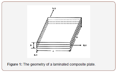
Figure 1 shows the geometry of a plate with rectangular orthotropic drawn in the Cartesian coordinates X, Y, and Z or 1, 2, and 3. The parameters used in such a plate are: (1) the length in the X-direction, (a); (2) the length in the Y – direction (i.e. breadth), (b); and (3) the length in the Z – direction (i.e. thickness), (h).
Fundamental equations of elasticity
Classical laminated plate theory (CLPT) is selected to formulate the problem. Consider a thin plate of length a, breadth b, and thickness h as shown in Figure 2(a), subjected to in – plane loads Rx, Ry and Rxy as shown in Figure 2(b). The in – plane displacements u (x,y,z) and v (x,y,z) can be expressed in terms of the out of plane displacement w (x,y) as shown below:

The displacements are:
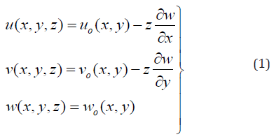
Where uo, vo and wo are mid – plane displacements in the direction of the x, y and z axes respectively; z is the perpendicular distance from mid – plane to the layer plane
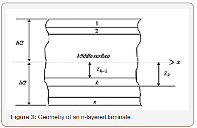
The plate shown in Figure 2(a) is constructed of an arbitrary number of orthotropic layers bonded together as in Figure 3.
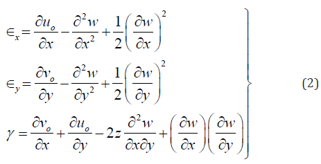
The strains are:
The virtual strains:
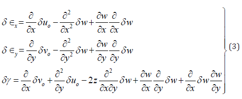
The virtual strain energy:

Where,

If we neglect the in-plane displacements uo and vo and considering only the linear terms in the strain – displacement equations, we write:
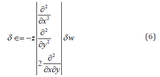
The Numerical Method
The finite element is used in this analysis as a numerical method to predict the buckling loads and shape modes of buckling of laminated rectangular plates [12,13]. In this method of analysis, four – nodded type of elements is chosen. These elements are the four – nodded bilinear rectangular elements of a plate. Each element has three degrees of freedom at each node. The degrees of freedom are the lateral displacement (w), and the rotations (ϕ) and (ψ) about the (X) and (Y) axes respectively.
The finite element method is formulated by the energy method. The numerical method can be summarized in the following procedures:
• The choice of the element and its shape functions.
• Formulation of finite element model by the energy approach to develop both element stiffness and differential matrices.
• Employment of the principles of non – dimensionality to convert the element matrices to their non – dimensional forms.
• Assembly of both element stiffness and differential matrices to obtain the corresponding global matrices.
• Introduction of boundary conditions as required for the plate edges.
• Suitable software can be used to solve the problem.
For an n noded element, and 3 degrees of freedom at each node.
Now express w in terms of the shape functions N (given in Appendix (B)) and nodded displacements ae, equation (6) can be written as:

and

The stress – strain relation is:

Where C are the material properties which could be written as follows:
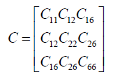
Where Cij are given in Appendix (A).

Where V denotes volume.

Where  is the bending stiffness, and Ke is the element stiffness matrix which could be written as follows:

The virtual work done by external forces can be expressed as follows: Refer to Figure 4.
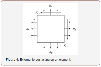
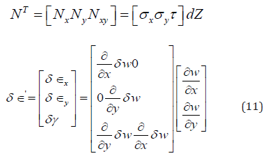
Denoting the nonlinear part of strain by δϵ’

Where
Hence,

This can be written as:

Now 
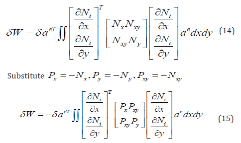
Therefore, equation (15) could be written in the following form:
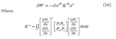
KD is the differential stiffness matrix known also as geometric stiffness matrix, initial stress matrix, and initial load matrix.
The total energy:

Since δ ae is an arbitrary displacement which is not zero, then

Now let us compute the elements stiffness and the differential matrices.
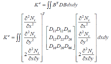
The elements stiffness matrix can be expressed as follows:

The elements differential stiffness matrix can be expressed as follows;

The integrals in equations (19) and (20) are given in Appendix (C).
The shape local co – ordinate for a 4 – noded element is shown below in Figure 5.
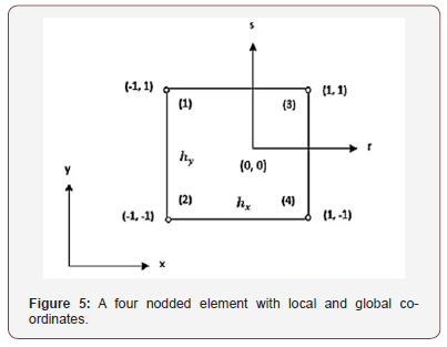
The shape functions for the 4 – noded element expressed in global co – ordinates (x,y) are as follows:

The shape functions in local co – ordinates are as follows:

The integrals of the shape functions in local co – ordinates are as follows:
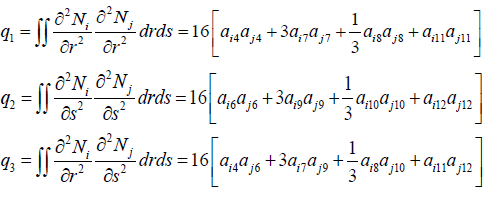
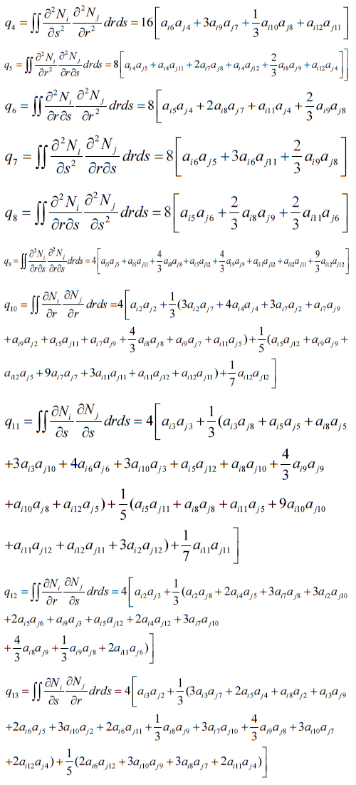
The integrals of the shape functions in global co – ordinates are as follows:
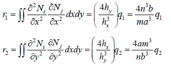
In the previous equations  where a and b are the lengths of the plate along the x – and y – axis respectively. n and m are the number of elements in the x – and y – directions respectively.
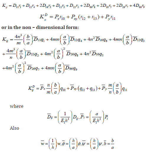
The elements of the stiffness matrix and the differential matrix can be written as follows:
The transformed stiffnesses are as follows:
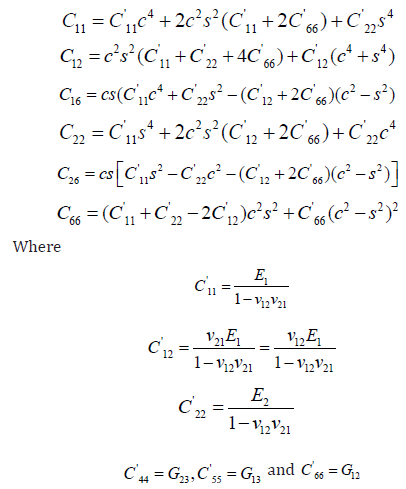
E1 and E2 are the elastic moduli in the direction of the fiber and the transverse directions respectively, v is the Poisson’s ratio. G12, G13, and G23 are the shear moduli in the x – y plane, y – z plane, and x – z plane respectively, and the subscripts 1 and 2 refer to the direction of fiber and the transverse direction respectively.
The Numerical Method
In the present analysis the lamination scheme of plates is supposed to be symmetric, anti – symmetric and quasi – isotropic.
Table 1: The first five non – dimensional buckling loads 2 3 1 P = Pa / E h of symmetric cross - ply (0/ 90/ 90/ 0) and anti-symmetric cross – ply (0/ 90/ 0/ 90), and symmetric angle - ply (45/ -45/ -45/ 45) and antisymmetric angle – ply (45/ -45/ 45/ -45) laminated plates with a / h = 20 , and 1 2 E / E = 5 .
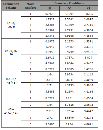
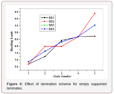
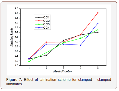
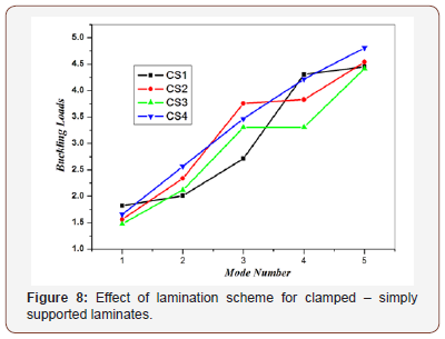
Four lamination schemes were considered which are symmetric and anti – symmetric cross – ply and angle – ply laminates. Table 1 gives a comparison between the non – dimensional buckling loads for all lamination schemes. The results are shown graphically in Fig. 6. The thickness of all layers is assumed equal, the length to thickness ratio (a/h=20), and the modulus ratio (E1/E2=5). It is noticed from Table 1 and Figures 6-8 that the values of the non – dimensional buckling loads for both symmetric and anti – symmetric lamination are slightly different, except for symmetric and anti – symmetric angle – ply laminates which are exactly the same. Because of this fact, the rest of the upcoming effects will be discussed for symmetric case only. The results indicate that the symmetric laminate is stiffer than the anti – symmetric one. This phenomenon is caused by coupling between bending and stretching which lowers the buckling loads of symmetric laminate.
Tables 2 & 3 show the buckling load of quasi – isotropic rectangular composite plate with a/h=20, a/b=1 and different modulus ratios (E1/E2=40 and 5). The buckling load is highly influenced by its boundary conditions. The buckling load of the quasi – isotropic (0/+45/-45/90) rectangular composite plate with CC type boundary condition is 1.5 times higher than the buckling load of the composite plate with CS type boundary condition and more than 3 times of SS type boundary condition.
Table 2:The first three non-dimensional buckling loads of quasi-isotropic (0/+45/-45/90) laminated plates with a / h = 20 and 1 2 E / E = 5

Table 3: The first three non-dimensional buckling load of quasi-isotropic (0/+45/-45/90) laminated plates with a / h = 20 and 1 2 E / E = 5 .

Conclusion
A Fortran program based on finite elements (FE) has been developed for buckling analysis of thin rectangular laminated decks plates using classical laminated plate theory (CLPT). The problem of buckling loads of generally layered composite plates has been studied. The problem is analyzed and solved using the energy approach, which is formulated by a finite element model. In this method, quadrilateral elements are applied utilizing a four noded model. Each element has three degrees of freedom at each node. The degrees of freedom are lateral displacement (w), and rotation (ϕ) and (ψ) about the x and y axes respectively. The finite element model has been formulated to compute the buckling loads of laminated plates with rectangular cross – section and to study the effects of lamination scheme on the non – dimensional critical buckling loads of laminated composite plates. New results have been presented. These results show that the symmetric laminate is stiffer than the anti – symmetric one. This phenomenon is caused by coupling between bending and stretching which lowers the buckling loads of symmetric laminate.
To read more about this article...Open access Journal of of Engineering Sciences
Please follow the URL to access more information about this article
To know more about our Journals...Iris Publishers
To know about Open Access Publishers


No comments:
Post a Comment