Authored by Mohammad Sadegh Marefat*,
Abstract
One type of structural systems that has received growing attention worldwide consists of flat slabs supported by steel columns. A key issue in these systems is the connection between slab and column. Although details for the connections of non-prestressed slabs are published frequently, but little details are reported for post-tensioned ones. In an experimental program, new details are proposed and examined for the connection of post-tensioned flat slab to edge steel column. The details include steel plates at the bottom and top of the slab, vertical stiffeners and vertical shear bolts. The connection is examined under cyclic lateral load test. The connection shows satisfactory seismic behavior, exhibits stable nonlinear response up to 3.5%drift ratio, and sustains gravity load capacity under relatively large lateral drift. To evaluate the effect of different details, a finite element model is developed and calibrated by the test results. According to the model, the effect of longitudinal and transverse arrangement of post-tensioning tendons and the level of prestressing of slabs are investigated. The study shows that the arrangement of banded tendons in the longitudinal direction and distributed in the transverse direction exhibits higher load capacity (about 20%) relative to the reverse arrangement (distributed in the longitudinal direction and banded in the transverse direction). The test also shows that increasing the average prestressing level from 1 MPa to 1.75 MPa results in an increase of about 30% of the load capacity of the connection. In this article, details of the studies and the obtained results are reported.
Keywords: Post-tensioned flat slab; Steel column; Connection details; Cyclic load test; Prestressing level; Tendons arrangement
Introduction
One type of structural systems that has received growing attention worldwide consists of flat slabs supported by steel columns. The use of flat slabs has become popular for several reasons such as relatively high fabrication speed, ease of construction, and lower execution costs. The flat slabs are generally either post-tensioned (PT) or non-prestressed (RC). The use of PT slab is rapidly increasing due to reduction of slab thickness and the possibility to build relatively large spans caused by deflection and crack control. This type of slab is generally supported by reinforced concrete columns, but steel columns are also increasingly used due to advantages such as higher fabrication speed and favorable steel ductility. In recent years, several studies [1-8] have been conducted on RC flat slab to steel column connections, where steel shear head has been used typically as the main shear bearing component. But in the post-tensioned slab, the use of shear heads and embedded profiles face the problem of intersection with post-tensioning tendons. The tendons have variable profiles and may intersect the shear heads, especially at the edge column connection. On the other hand, the presence of integrated profiles is essential for a ductile shear behavior. But, specific details have been rarely reported for this type of connection in the literature. New details have been proposed in this study for the post-tensioned flat slab to steel column connections. These details include top and bottom steel plates, vertical stiffeners, and post-tensioned high-strength bolts. The proposed connection can provide sufficient ductility under relatively large lateral motions in addition to creating suitable force transfer paths from the flat slab to supports. Considering the fact that flat slab to column connection is vulnerable to excessive stresses and earthquake-induced deformations [9-11], provisions of ACI 318 [12] limit the use of post-tensioned flat slabs for gravity loads only in all seismic zones. However, due to deformation compatibility requirements, the connection should be able to maintain its gravity bearing capacity without brittle failures such as punching shear, up to the design drift target. To evaluate the proposed details, a test specimen has been examined under reversed-cyclic lateral load with increasing amplitudes. The test reveals satisfactory seismic performance of the connection. To expand the test results and to study various conditions, a finite element model has been developed and verified by the test. The study indicates that both tendons arrangement and prestressing level strongly influence not only ductility but also load bearing capacity of the connection. The results of this study are discussed in the following sections.
Review of Previous Studies
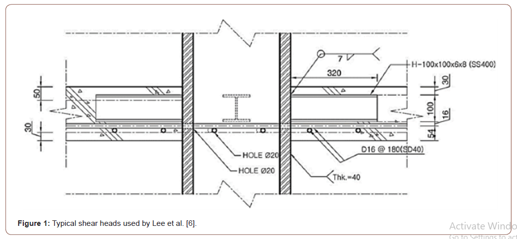
Previous studies [13-17] indicate that lateral ductility capacity of flat slab-column connections is strongly influenced by gravity load, and lateral displacement capacity decreases as gravity load increases. Also, ductility of the connection will increase if shear reinforcement is used [10,13,18]. Therefore, ACI 318 provisions [12] have limited the design drift values for the post-tensioned slab-column connections in accordance with the gravity shear ratio (GSR). It is noteworthy that the post-tensioned flat slab connections have higher lateral displacement capacity relative to non-prestressed flat slabs [13,19,20]. Thus, ACI 318-19 [12] has provided a separate relationship for the post-tensioned flat slab connections. One type of flat slab systems is that supported by steel columns. Studies of these types of T or I-shaped profile [1-6] where, sometimes, top and/or bottom steel plates have been used [1-3] are reported. In some details [3,6], holes have been provided in the steel column for passing the top and bottom reinforcements through the column (Figure 1). It should be noted that the slab in these studies is of non-prestressed type (Figure 1).
Overall, according to the afore mentioned studies [1-6], the passage of bottom and top longitudinal reinforcements through the column, plays a key role in improving the post-punching behavior and resistance of the connection. Also, the use of bottom steel gusset plate in the first place, and the use of bottom and top fixing plates in the second place, have a significant effect on the connection performance. These measures, in addition to providing favorable ductility, prevent local failures that can occur in the concrete slab in the connection area and adjacent to the column. Another parameter affecting the behavior of these connections is shear arm, that is, the shear strength increases with increasing shear arm.
The Proposed Details
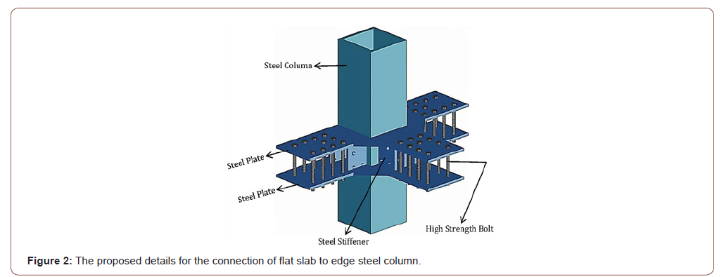
In this study, specific details for post-tensioned flat slab to steel column connections are proposed. The connection consists of top and bottom steel plates welded to the steel column, vertical stiffeners welded to the steel plates and to the column, and posttensioned high-strength bolts that connect the steel plates to the PT slab as is shown in Figure 2. In the vertical stiffeners, holes have been provided for passages of tendons and bottom reinforcements as well as top reinforcements through the confined region of the column. The high-strength bolts are post-tensioned after obtaining sufficient concrete strength (Figure 2).
Lateral Load Test of the Proposed Connection
Test specimen
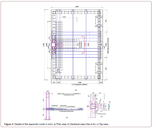
A conventional eight-story residential building with five spans of 8.5 m in perpendicular directions with story height of 3.16 m was designed as the prototype building. The post-tensioned flat slabsteel column system has been used as the gravity force resisting structure and a ductile reinforced concrete wall has been used as the lateral force resisting system. It has been assumed that this building has been located in an area with high seismic hazard. The slab thickness is 240 mm and the span-to-thickness ratio is 35.8 which is in the conventional range of 35~45 for PT flat slab. As recommended by ASCE/SEI 7-16 [21], the dead load (including slab self-weight and decking), the live load, and the portions’ load have been considered, respectively, 7.1 kPa, 2 kPa, and 0.75 kPa. According to common design procedure of the post-tensioned slabs, banded tendons have been used in one direction and distributed tendons in the perpendicular direction. The average compressive stress in the slab (fpc) is 1.23 MPa, which is in the range of 0.9~3.44 MPa recommended by ACI 318 [12]. The scale of the experimental specimen is half (1/2), which represents the post-tensioned flat slab to steel edge column connection of the prototype specimen. The inflection point is assumed to be in the middle of the column height and approximately in the middle of the slab span, parallel to lateral load direction. The banded arrangement has been used in the direction of lateral load and the distributed arrangement in the direction perpendicular to it. The dimensions of the posttensioned slab are 2.2 m in the direction of lateral load and 3 m in the perpendicular direction and the slab thickness is 120 mm. The steel column is a hollow square with the dimension of 180 mm and thickness of 15 mm. The length of the stiff zone (length of the stiffeners) is 100 mm from the column faces, the length of the rectangular part of the steel plates is 220 mm and the thickness of the steel plates and stiffeners is 10 mm. 10 M12 bolts are used on each rectangular part of the plate (30 bolts in total). These bolts are post-tensioned to 60 kN. The clear cover of concrete in the specimen is 12 mm. Details of the test specimen are observed in Figure 3 (Figure 3).
Material properties
The design compressive strength of the concrete is 40 MPa. The concrete cubic compressive strength on the test day is 47.5 MPa. The ribbed reinforcement is 10mm in diameter with design yielding stress of 400 MPa. Full-threaded bolts with a diameter of 12 mm and ultimate design stress of 1000 MPa have been used in the connection. For post-tensioning the slab, seven-wire strands with 12.7 mm diameter and ultimate design stress of 1861 MPa have been used. The tendons (the seven-wire strands) coated with grease and embedded in polyethylene tubes with a diameter of 14.9 mm. The measured properties of the steel materials used in the test specimen have been summarized in Table 1 (Table 1).
Table 1:Steel material properties.

Test setup
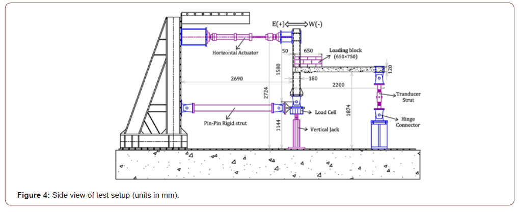
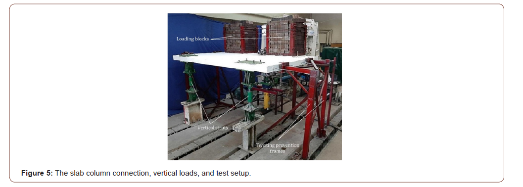
The test setup was constructed to enable the proposed connection to be tested under lateral loading combined with constant gravity load. The test setup with the specimen in position is shown in Figures 4, 5. The base of the column has been connected to a hinge that represents the inflection point of the column. There is a load cell below this hinge to measure axial force of the column. Below this load cell, there is a 1000 kN hydraulic jack attached to the strong floor. In order to simulate and provide boundary conditions for lateral loading, two vertical struts have been located at the corners of the slab, in the opposite side of the column. The gravity loads and the shear demand applied to the connection zone have been simulated by placing loading blocks on the top surface of the slab as well as by lifting up the base of the column using the 1000 kN hydraulic jack.
Lateral loading history
Lateral loading history is shown in Figure 6. The lateral loading is in the form of reversed-cycle, displacement- control, and monotonically increasing drift ratio from 0.2% to 6% (according to ACI 374.1 recommendations [22]). Lateral displacements are applied above the column using a 250 kN hydraulic displacement jack. Twisting prevention frames have been placed on both sides of the specimen. These frames are attached to the slab by lubricated roller bearings (Figures 4- 6).

Crack Patterns and Observed Damages
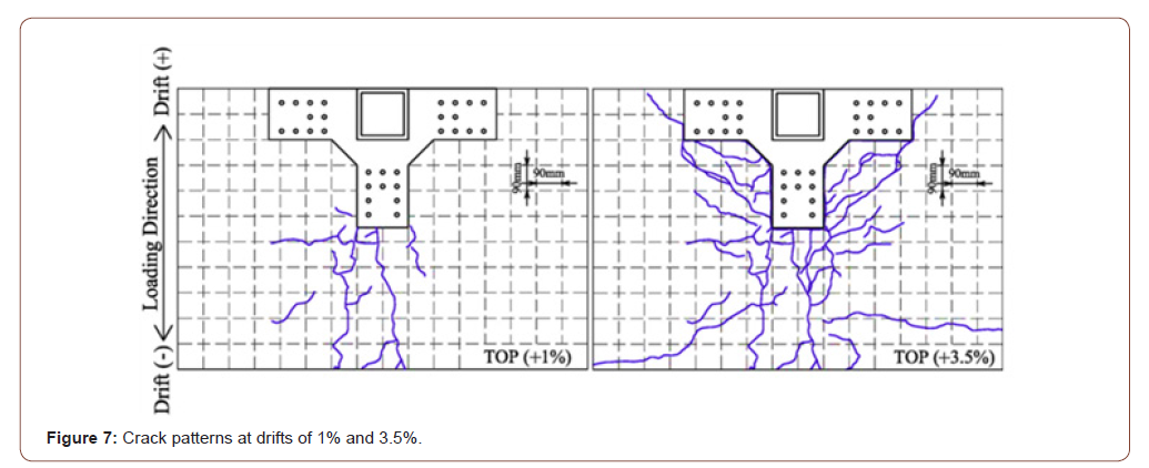
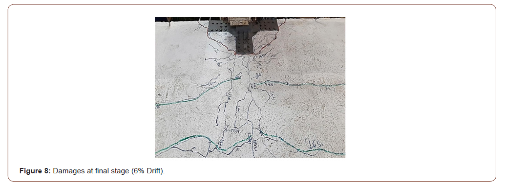
Crack patterns and damages at two stages (%1 and 3.5% drift) are shown in Figure 7 and the observed damage at the final stage (6% drift) are illustrated in Figure 8. Overall, the following results have been obtained: the specimen remained uncracked under full gravity load before applying lateral load which indicates the complete post-tensioning of the slab. Slab cracking began in front of the steel connection by applying lateral load at a drift ratio of about 1%. From 1% to 3.5% drift ratio, most of the cracks are shear flexural in nature. From a drift of 3.5% up to 4.5%, the cracks extend around the connection and punching shear cracks develop throughout the depth of the slab. The pattern of cracks has not changed but the width has increased from the drift of 4.5% up to 6%. It is noteworthy that no significant failures and/or concrete crushing are observed throughout the test (Figures 7, 8).
Lateral Load versus Lateral Drift
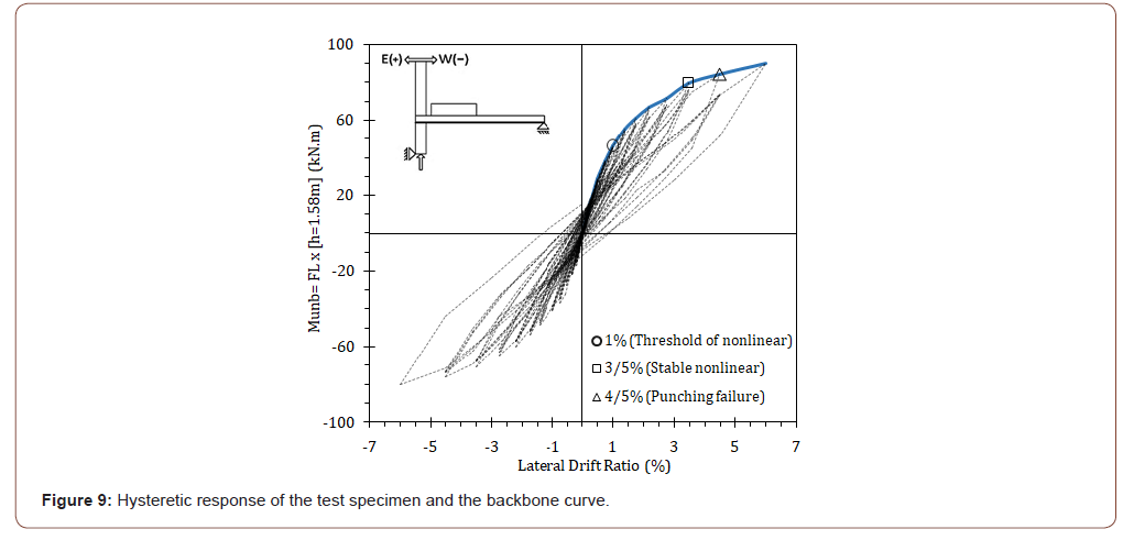
The hysteretic behavior of the specimen is illustrated in Figure 9. The positive drifts indicate both tension on the top surface of the slab and column displacements towards the outside of the slab span. As previously stated, the specimen has remained uncracked under full gravity load combined with lateral drift ratio up to about 1%. Figure 9 shows that cycles of the hysteretic behavior up to about 1% drift are almost elastic and linear. The threshold of nonlinear behavior is about 1% drift, and this drift can be defined as the linear elastic limit. Clear nonlinear behavior is formed at 1% drift, and nonlinearity is associated with the formation and opening of cracks. Three important stages may be recognized in the nonlinear response. This is illustrated in Figure 9on the backbone curve. According to this Figure, after a drift1%, the specimen enters the nonlinear phase and its stiffness and strength reduce with increasing lateral displacement. The ascending nonlinear shape continues up to a drift of 3.5%. A slight increase in strength is observed after 3.5% drift, and then, the specimen enters almost a plastic phase to reach a drift of 6% (end of test). Also, based on damages, the main punching shear cracks are observed substantially around the connection and near the edge of the slab at 3.5% drift. While, continuous and throughout punching cracks are formed around the connection at a drift of 4.5%.Therefore, a drift of 3.5% and 4.5% may be defined as the final stage of stable nonlinear behavior and the punching failure limit, respectively (Figure 9).
Numerical Modeling
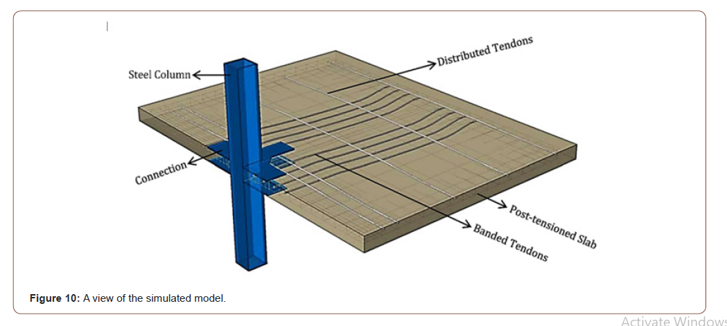
In this section, the finite element model and details of the simulation are described. The concrete damaged plasticity model has been used for concrete modeling [23]. The compressive stress-strain relationship of concrete has been calculated from the experimental relationship presented in [24].The tension stiffening effect has been modeled using the stress-strain relationship. The value of strain corresponding to the tensile failure (εtck) has been considered triple of the cracking strain (εtck=3ft′/Ec). The module of elasticity of concrete (Ec) has been calculated from the proposed relationship in ACI 363 [25]. The tensile concrete strength (ft′) has been obtained from the relationship ft′=0.62√fc′ (ACI 318 [12]), and the dilation angle has been considered 30 degrees. The linearly elastic-perfectly plastic model has been used for modeling of bonded reinforcements and steel plates. The experimental model presented in [26] has been employed for modeling of the nonlinear stress-strain behavior of post-tensioning tendons. The three-linear model presented in [27] has been used for modeling of high-strength bolts. The behavior of tendon sheathing has been considered elastic with an elastic hardening equal to the elastic module of concrete. It should be noted that the module of elasticity of steel materials (Es) is approximately equal to 200 GPa. In the numerical study, each bonded reinforcement and each bolt have been simulated using two-node linear truss elements (T3D2). The three-dimensional eight-node first-order brick elements with the reduced integration rule (C3D8R) have been used for the rest elements including slab, steel plates, tendons and sheaths. Seven layers of brick elements have been used for thickness of the slab. It has been assumed that there was a perfect bonding between reinforcements and concrete slab, and between sheaths and concrete slab. As mentioned before, the tendons were coated with grease and embedded in polyethylene sheaths. This unbonded condition could be simulated by using “surface-to-surface contact” formulations, in which the outer surface of the tendon is in contact with the inner surface of the sheath. In this contact formulation, the tangential and normal behavior of the contact surfaces has been selected to be frictionless contact and hard contact, respectively. The tendon’s end anchorage to the concrete slab has been simulated by “MPC-Beam” (Beam Multiple-Points Constraint), in which the surface of each tendon’s end has been connected to the control point (the center of the tendon’s surface) by rigid beams. Details of the simulated model are shown in Figure 10 (Figure 10).
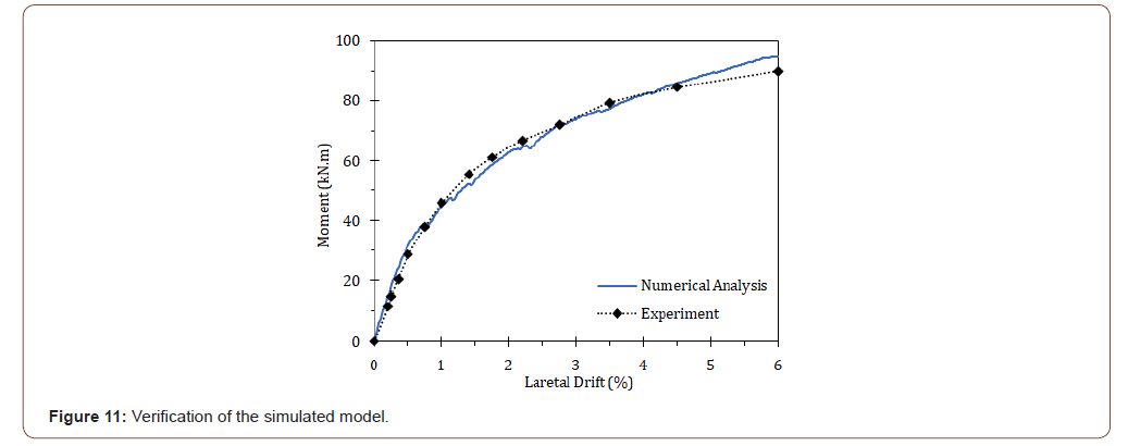
The nonlinear analysis of the proposed simulation has been performed in four stages, that is, application of bolts prestressing, application of tendons prestressing, application of gravity loads, and then, application of monotonic lateral load. The monotonic nonlinear analysis has been performed in displacement- control mode. The connection behavior under lateral loading is shown in Figure 11. As observed, the response of the connection, especially to the limit of punching failure (4.5% drift), is relatively close to the test results (Figure 11).
Effect of Tendons Arrangement
As mentioned earlier, according to common design procedure of the post-tensioned slabs, banded tendons are used in one direction and distributed tendons in the perpendicular direction. In the test specimen and its numerical simulation, the tendons has been banded in the direction of lateral loading (longitudinal direction) and distributed in the perpendicular direction to it (transverse direction). This arrangement has been defined as B-D in this study, and in reverse, the arrangement of distributed in the longitudinal direction and banded in the transverse direction has been defined as D-B. To evaluate the effect of tendons arrangement, a model with D-B and another one with B-D have been simulated and analyzed. The behavior of B-D and D-B arrangements is shown in Figure 12 (Figure 12).
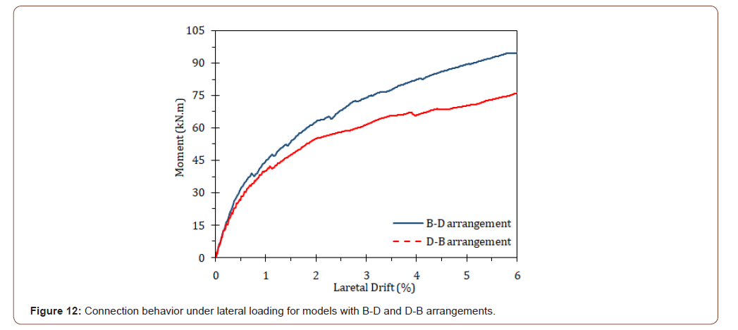
As can be observed in Figure 12, the resistance of the B-D arrangement has significantly increased compared to D-B. That is, the resistance of B-D at a drift ratio of 4.5% is about 25% higher than the that of D-B. The increase values of resistance for the connection with B-D compared to D-B, at drifts of 2%, 3.5%, and 4.5% are demonstrated in Table 2 (Table 2).
Table 2:Increase of the resistance of B-D compared to D-B.

In total, the study shows that the behavior of the connection is significantly affected by the tendons arrangement. That is, the arrangement of banded tendons in the longitudinal direction (lateral loading direction) and distributed in the transverse direction is more favorable in terms of higher lateral load capacity (up to 18%)relative to the reverse arrangement (distributed in the longitudinal direction and banded in the transverse direction).
Effect of Prestressing Levels
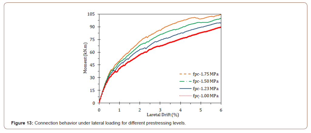
To evaluate the effect of prestressing level on the behavior of the proposed connection, four models with the average compressive stress (fpc) of 1 MPa, 1.23 MPa, 1.5 MPa, and 1.75 MPa have been simulated and analyzed. The average compressive stress of 1.23 MPa is that of the simulated experimental model. It may be mentioned that the average stress recommended by ACI 318 [12] is between 0.9 MPa and 3.44 MPa, and the values in common design procedure, vary between 1.0 MPa and 1.9 MPa. The behavior of the mentioned models under lateral loading is shown in Figure 13 (Figure 13).
As can be seen in Figure 13, the resistance of the connection has significantly increased by increasing prestressing level. That is, the resistance at drifts of 3.5% and 4.5% has increased about 26%and 29% respectively, by increasing the average compressive stress from 1 MPa to 1.75 MPa. The increase value of resistance for different prestressing levels compared to that of 1MPa, at drifts of 2%, 3.5% and 4.5% are shown in Table 3 (Table 3).
Table 3:Increase of resistance for different prestressing levels compared to stress of 1Mpa.

In total, the study shows that prestressing level of the slab strongly affects lateral load capacity of the proposed connection. That is, by increasing the prestressing level from 1 MPa to 1.23 MPa and 1.75 MPa, the load capacity increases by less than 20% and 30%, respectively, over the range of 2 to 4.5 drift ratios.
Conclusion
In this study, specific details have been proposed for the connections of post-tensioned flat slabs to steel columns. The details consist of top and bottom steel plates welded to the steel column, reinforced by vertical stiffeners, and connected to the slab with post-tensioned high-strength bolts. These details have advantages such as avoiding intersection of the connection components with post-tensioning tendons, speed of erection, and cost saving. To examine the details, a half scale specimen is tested under reversedcyclic loading with increasing amplitudes. To expand the study in different conditions, a finite element model has been developed and verified using the test results. According to model, the effect of tendons arrangement and prestressing level on the behavior of the proposed connection have been evaluated. The test shows:
1. The proposed connection remains elastic up to a drift ratio of 1%, and this drift may be considered as the threshold of nonlinear response.
2. A drift of 3.5% may be considered as the stable nonlinear limit for the connection.
3. A drift of 4.5% may be assumed as the stage of punching shear failure.
4. The details could tolerate relatively large lateral displacements up to 6% drift without losing gravity bearing capacity.
The numerical analysis indicates that:5. The arrangement of banded tendons in the longitudinal direction and distributed in the transverse direction is more favorable in terms of higher lateral load capacity (up to 18%) relative to the reverse arrangement (distributed in the longitudinal direction and banded in the transverse direction).
6. Prestressing level of the slab strongly affects lateral load capacity of the proposed connection. That is, by increasing the prestressing level from 1 MPa to 1.23 MPa and 1.75 MPa, the load capacity increases by less than 20% and 30%, respectively, over the range of 2% to 4.5% drift ratios. Based on this study, the proposed details for the connection of post tensioned slabs to steel columns have exhibited a favorable seismic performance. The behavior has been significantly influenced by prestressing level and tendons arrangement.
To read more about this article...Open access Journal of Civil & Structural Engineering
Please follow the URL to access more information about this article
To know more about our Journals...Iris Publishers


No comments:
Post a Comment