Authored by Sokolov NS*,
Abstract
The construction of facilities in cramped conditions requires a special approach to the need to develop and implement measures to ensure the safe operation of the buildings surrounding the building within the limits of geotechnical influence. Builders often neglect the impact of the new facility technology on the possible negative effects (cracks on facades due to uneven precipitation, heels, etc.) of the buildings in use. The term «minimum price» is still used when part of a building is erected below zero. This approach completely disregards the notion of «technical utility». At the same time the builders go to any tricks to reduce the cost. This «irrational» way of construction may eventually result in a substantial increase in the cost of constructing a zero part of a building and, as a general rule, in a longer construction period (agreement on a new project as a result of substitution of another geotechnical technology, passing of new construction expertise). This article examines one negative case from the geotechnical practice of constructing 16 storey dwellings next to an existing five-storey dwelling house.
Keywords:Geotechnical construction; Irregular precipitation; Ground anchors; Excavation fencing; Electrical discharge technology; EDT piles
Introduction
Construction in cramped conditions is the most problematic from the point of view of the technology of construction production of parts below zero mark. Design and construction should include a set of measures to ensure the safe operation of existing buildings. Modern geotechnical technologies are successful in meeting such challenges [1-13]. This article discusses a negative example of the construction of a multi-storey apartment building next to an existing house.
Methods and Materials
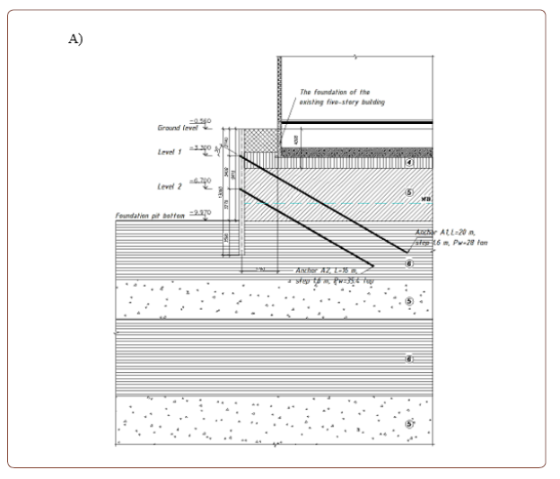
The new construction facility is a single cast-in-place reinforced concrete block in the shape of a rectangle. The above-ground part of the construction facility consists of a technical floor and 16 aboveground floors. The structural scheme is a cast-in-situ concrete-free frame with self-supporting outer walls of foam-concrete blocks supported by inter-story floors. The ceilings and coatings are made of cast-in-situ reinforced concrete. The structural solution of the foundation is provided as a cast-in-place reinforced concrete foundation plate. The depth of the foundation pit varies from 9.3 m to 9.6 m in various areas. The absolute level of the bottom of the foundation pit is 175.30 m of the Baltic Normal Height System (BAS). The width of the foundation pit is 27.0 m, and its length is 40.0 m. In accordance with para. 9.36 SP 22.13330.2011 “Updated edition of SNIP 2.02.01-83* “Soil bases of buildings and structures” the radius of the new construction impact zone is equal r36 =4·Hк for a pit to be excavated with steel pipe fencing. Thus, the impact zone for the specific case was 38.4 m. A five-story two-access apartment building is located in the area. The technical condition category of the adjacent residential building according to the reports on the results of the technical inspection carried out shall be considered satisfactory according to the existing regulatory documents. The spatial stiffness of the apartment house is ensured by hard disks of inter-level floors and coatings, blocks of staircases. In plan the object has dimensions of 54.0x12.75 m and 17.0 m in height. The foundations are made of prefabricated tapes made of concrete blocks of FBS basement walls 400-500 mm thick laid on a cast-inplace reinforced concrete belt erected on the foundation slabs of the FL. Foundation depth varies from 2.79 to 3.05 m. The walls of the building are made of silicate brick 510.0 mm thick on cementsand solution. The inner load-bearing walls, 380.0 mm thick, are also made of silicate brick, and the inter-story and attic floors are made of reinforced concrete multi-hollow slabs 220.0 mm thick. In the initial version, the foundation walls of the foundation pit are designed as an unfastened sheet pile wall using two tiers of Atlant ground anchors (Figure 1A).
For this case, steel pipes with a cross section of 530x8 by GOST 10704-91 “Electrically welded steel line-weld tubes. Schedule” with a step of 1.0 m are used for the sheet wall, and pipes with a direction of “Z” are arranged with a step of 0.8 m. They are also filled with heavy concrete in the immediate vicinity of the building. Top of sheet pile wall tubes elevation is assumed variable from 184.54 m to 184.84 m (BAS). The bottom of the pipe fencing along the axes “1”, “A” and “12” is located at the elevations from 171.54 to 171.84 m BS with their length of 13.0 m, along the axis “Z” bottom of the pipe fencing stands at 166.84 m (BAS) with pipe length of 18.0 m. A board fence 40.0 mm thick is designed between the pipes of the fence. At the request of the developer customer, we (LLC FORST Research and Production Company) have been instructed to develop an alternative variant of the unfastened sheet pile wall using steel pipes of the same cross-section dimensions but using ground anchors of three tiers of prepared using electric-discharge technology (EDT anchor) (Figure 1B).
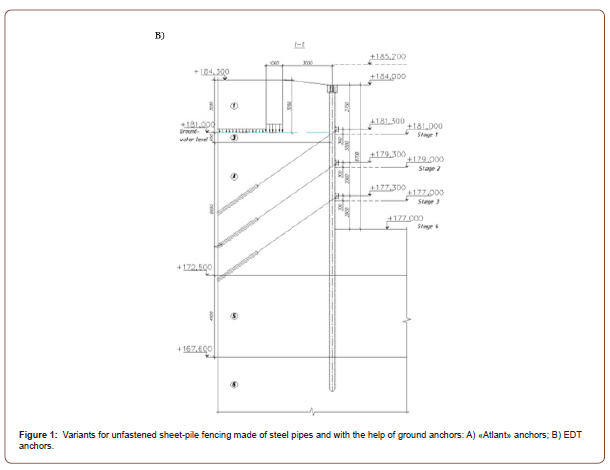
The design burial depth of the steel pipes was deeper than the original design. In addition, we have designed sheet pile wall using drilled injection EDT piles with a diameter of 350 mm with a cast-in-situ reinforced concrete girder on the top of the piles at the adjoining areas to the existing buildings. The planned wall is a solid cast-in-place reinforced concrete structure that would prevent the soil from sloughing under the foundations of the existing apartment building during excavation.
Results and Discussion
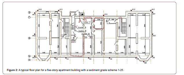
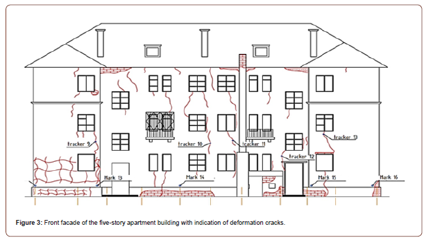
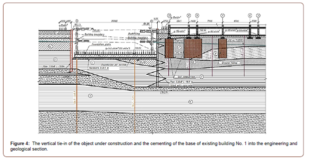
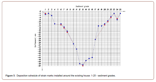
The customer having studied both variants of the fence of the pit has come to an unexpected and strange conclusion about the necessity of cheaper design of the pit fence. In this case, the meaning of “technical feasibility” is completely neglected, although economic efficiency is significantly acquired. Thus, they were ordered a third version of the pit fencing project, but without anchoring, using, as in previous designs, steel pipes and steel shootings on two levels to replace the ground anchors. At the same time, the developed project excludes the construction of a solid sheet pile wall (it is one of the main buried structures ensuring the foundation stability under the foundations of an existing residential house) on the site of attachment to the existing residential house. A 50B2 double-stranded spreader belt is designed to treat soil forces evenly and to offend them. It should be noted that used steel pipes were used as the construction material for the shootings. When they are executed at one level only. The used firing pipes suffered significant deformations (bends, cross-sectional collapses, as well as soil and asphalt holes) during the rupture of the foundation pit, which resulted in horizontal deformations of the sheet pile wall made of steel pipes towards the pit. At the same time, the absence of solid barrier sheet walls at the areas of connection to the existing apartment building during excavation of the foundation pit caused the soil to fall out from under the foundation footing. As a result, the existing dwelling house was immediately vertically deformed, as evidenced by the deformation cracks that appeared on the outer surfaces of the facades, progressing in time. The urgently organized geotechnical monitoring of the vertical movements of sediment marks (Figures 2 & 3) confirmed the worst fears. A part of the dwelling house on the side of the new construction of the settlement and continues to deform (Figure 4). The client urgently decided to develop a project for cementing the deformed part of the foundation and immediately implement it (Figure 4). Geotechnical monitoring results show that even after the geotechnical work for cementing the foundation, foundation deformations continued to develop. All the maximum allowable strains have already been exceeded. For example, the most deformed sediment grade received a vertical displacement of 52.0 mm (Figure 5) at an allowable value of 20.0 mm. In order to avoid further deformation of the existing dwelling house, the customer again requested us (LLC NPF FORST) to develop a project for reinforcement of the deformed base and performance of geotechnical works for its reinforcement. Electrodischarge geotechnical technology for arrangement of drillinginjection piles (EDT piles) was used as the most suitable for solving problems in restricted conditions. Only by strengthening the foundations of the troubled dwelling house using this geotechnical technology has it been possible to prevent further deformations of the foundation, as shown by 1) geotechnical forecast and 2) results of geotechnical monitoring of vertical movements of sediment marks. Table 1 below shows the steps from the beginning of construction to the resolution of the issues on strengthening the foundation of the deformed five-story apartment building (Table 1) (Figure 2-5).
Conclusion
1. In geotechnical construction in restricted conditions, disregard of the principle of “technical feasibility” in favor of achieving economic efficiency in most cases leads to impairment of the operational reliability of existing buildings and structures.
2. The so-called “economic efficiency” acquired may be substantially reduced to zero, or the final design of the pit fence may end up being much more expensive than the original design. Construction terms are guaranteed to be extended.
To read more about this article...Open access Journal of Civil & Structural Engineering
Please follow the URL to access more information about this article
https://irispublishers.com/ctcse/fulltext/errors-in-construction-of-facilities-in-restricted-conditions.ID.000667.php
To know more about our Journals...Iris Publishers
To know about Open Access Publishers


No comments:
Post a Comment